
The Finite Element Analysis approach to complex problems is at the core of many mechanical engineering solutions, as well as applications to other engineering disciplines. It can be employed to answer questions in design, such as:
There is no limit to the types of questions that can be explored within an FEA simulation. This very powerful tool is integral to our company’s design process.
Depending on the complexity of the scenario that needs to be analyzed, different tools can be employed:
We provide high quality finite element analysis services to clients from a variety of industries including manufacturing, transport, agriculture, construction, mining and energy, as well as integrating it as a tool into our design process.
Using applicable codes and standards as well as best practice methods, we are able to simulate a vast variety of mechanical, structural and thermal problems. We specialize in static structural, buckling, thermal and fatigue analyses.
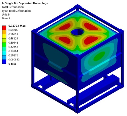
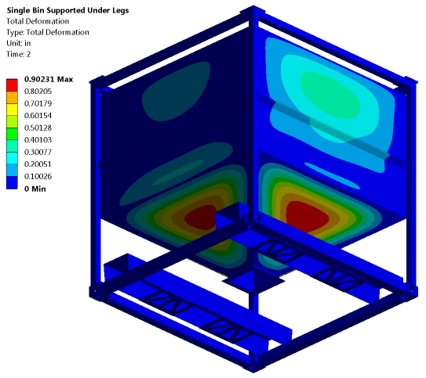
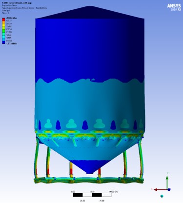
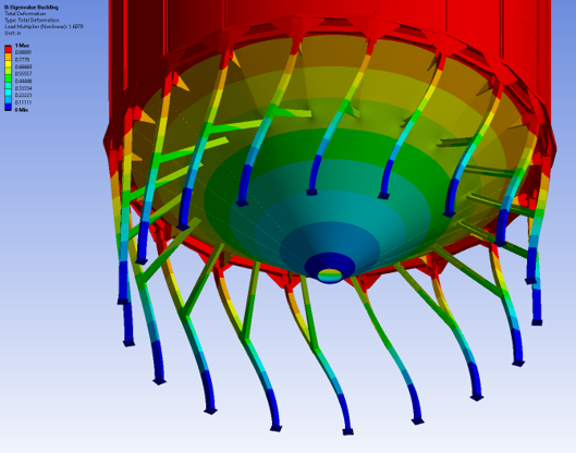
Our static structural capabilities include linear and non-linear material, geometry and contacts such as bonded and frictional, weldments, bolted structures and assemblies. We use linear or non-linear material models as required to simulate the elastic or elastic-plastic behaviour of metals. We use linear or non-linear analysis as required to simulate the change in stiffness of geometry as it deforms under an incrementally increasing load. We can analyze stability and buckling of complex shapes and structures.
Our ever-growing experience in numerical simulation using ANSYS – a powerful FEA software – makes us the ideal partner to run numerical simulations, including:
Often simply referred to as FEA, this analytical process entails the simulation of a physical component or part subjected to a load or changing condition in order to determine the effect of this very same load or changing condition on the component or part itself. By breaking the physical system into small discrete parts and looking at the effect on each small part through a numerical (mathematical) analysis the simulation creates a fully detail picture of the possible global effects. This is called the Finite Element Method (FEM).
The limit load is a special complex form of FEA. It is a non-linear FEA approach where the component material is not allowed to yield. As soon as any plastic deformation occurs in the simulation it stops and the whole system will re-calculate the small finite components. This requires very specific material models and load steps but the power is in the fact that the final displacement including all local plastic deformation is determined and if the system – model – is stable at the pre-determined safety factor multiple of the load – it can be safely assumed that the real part would be fine in service.
ProForma Winnipeg
1260 Border Street
Winnipeg, MB R3H 0M6
204-414-9107
ProForma Ontario
5063 N Service Road
Burlington, ON L7L 5H6
905-319-8867
info@proformaengineering.com
Copyright © ProForma Engineering. All Rights Reserved 2021
Website by Forest Online Marketing Solutions